Pre Installation Guide
Odyssey Performance 3-Step Pre-Installation Guide
1. Site Location
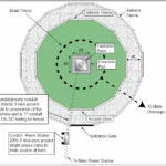
Choose an area that is convenient both for the horses and trainers while being easily accessible to 220v single-phase power (the recommended maximum distance from electrical breaker to control panel is 200ft or 61m). Before excavation, it is important to call your local utility companies to ensure that there are no underground pipes, cables, and wires etc. in the area.
Please see Figure 1 for horse exerciser location suggestions.

2. Foundation Installation
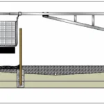
A solid foundation is paramount for trouble-free operation of the Odyssey Performance Trainer (see Figure 2). From the center of the chosen site excavate enough soil to pour a 6’x 6′ cement footing, approximately 6″ above the desired finished grade and to a depth that is below the frost line (if applicable) to prevent heaving during freeze/thaw cycles. Recommended concrete to be used is 15-20 MPa or 3000 psi with 20mm regular stone, no reinforcement in the pad is necessary, but may be added for extra strength.
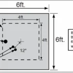
In addition, excavate a trench from the foundation site to the location of the control panel and another from your control panel to your power source. It is recommended that the control panel be situated adjacent to the main gate opposite the gate opening—this will ensure that horses can be easily lead into the exerciser while the control panel is manned by the trainer. The depth of this trench should meet local electrical code for buried wire. Install two 1″ PVC conduits from the control panel location to within 12″ from the center of the foundation and another 1″ PVC conduit from the power source to the control panel (Figure 3.). Placing a string in the conduits aids in ‘fishing’ the power cables from the control panel to the motor. Place a 1/2″ID 75psi water line offset 12″ from the center of the pad if a sprinkler system is to be installed (Figure 3). Before pouring the concrete, ensure that the foundation pad form is level to allow trouble-free operation of the exerciser. You will also need enough 30amp 220v 2-wire plus ground single phase cable to power the control panel (i.e. from your power location to the control panel), 20amp 3-wire plus ground cable to connect the exerciser’s motor to the control panel and 14 gauge 2-wire to connect the fencer to the control panel (consult an electrician if you are considering other cable options). Some installation and electrical requirements may vary depending on local codes. If using a center pole application, then under-gate cable will be used instead of the 14 gauge 2-wire.
3. Site Drainage
The area should be well drained to ensure that the footing you choose remains dry and that potential injuries from poor footing are avoided. If water can be seen “pooling” or standing water frequently occurs then you may wish to consider installing a drainage system. The surface should be graded towards the midpoint between the center of the machine and the exterior fence (see Figure 2). Drainage tile is then placed at the lowest point in a concentric circle between the concrete footing of the machine and the interior fence. From the circular drainage tile additional line(s) are added to carry the water away from the area. Overtop of the drainage tile use “A” gravel compacted to form a French Drain. Over this sub-base you may wish to use a geotextile fabric to separate the final footing material from the rock sub-base. Over the “A” gravel use a stone dust or Granular “D” material. This material should be compacted to form a type of road base material. Separation of the materials will greatly increase the lifespan of the drainage tile while preventing potential settling. The top footing material in specific to each riding discipline. Sand, bark chip, rubber are all used in the horse exercisers. Consult a drainage expert if you are unsure on how to proceed with drainage installation. Consult local riding ring or track builders about footing available in your area.
Tip: Make sure that your sub-base is level around the complete circle of the machine. Drainage should drain to the inside of the machine. After the sub-base is installed, the fencing should be installed before the top footing material.